
The design and making of a homemade fly tying vise.

The loyal visitors of the Global FlyFisher website have probably read previous articles of mine, such as Tom's reel and Tom’s line winder.
The interest in these items judged on the basis of the many positive responses I've gotten, has prompted me to make this article about designing and making of a fly tying vise.
Especially the layouts of the articles with the many pictures has been well received. Sometimes a picture says more than a half-page text, therefore this article also contains many explanatory pictures. But first a technical explanation and some background information.
Why make your own vise?
There are so many beautiful and good working vises on the market today, but like making your own fly fishing reels, the satisfaction it gives to design and making the vise is very rewarding, especially if the end result meets the expectations.
After using several vises for the past 35 years, I currently use a “Basic Stonfo Vise”, a very good vise for the small and medium hook sizes. For the bigger hooks (streamer hooks) I use an imitation “Regal Vise” with a huge clamping force on the hook, a very robust vise. And of course my homemade vise!


Hobby and challenge
For me it's a hobby in addition to fly fishing, to make fly fishing related products like fly reels, fly tying tools, linewinders and landing nets just to name a few.
When designing the vise, I wanted to combine other hobbies, namely fine metal work and fine woodworking/wood turning. The design had to be a combination of wooden and metal parts (aluminum, stainless steel) and some plastic parts. A nice challenge to make this technical, functional and aesthetic combination a success.
Principles and requirements
I had a number of principles and requirements put on paper too, which the result had to meet, some from experience with the use of several vises and other by own creativity.
- A design for small to medium hook sizes.
- Not a copy of an existing vise.
- A nice design (personal taste).
- A combination of exotic hard wood, metal and plastic.
- Fully adjustable and removable head with the fly still clamped in it.
- 360 degree rotating tying head, adjustable to the center line of the hook shank.
- Easy to disassemble parts.
- Parallel clamping of the jaws on the hook shank/bend.
- Not hardened but durable jaws for better grip and no damage to the hook.
- Replaceable jaws.
- All the parts must be manufactured by myself.
A pretty package of principles and requirements and as it turned out a big job to place everything in an acceptable design.
For a couple of years I had been thinking about manufacturing a vise, but something like that must be grown in your head. Various constructions and sketches were already made on paper, but the whole package had not yet taken shape. Such projects cost a lot of time, and with a full time job and only the evenings and the weekends to work on it, and then mainly throughout the fall and winter months, it is a time consuming project.

Operation of a vise
If you have worked with different vises and attentively and technically have looked at other vises, then you know how they work and how they clamp the hook. Most vises have inner conical constructions that causes the jaws to squeezed together. This can be done by the pushing motion of the jaws into a conical section or by pulling it in a conical section. This will close the jaws around the hook shank.
On the drawing you can see the schematic of how the jaws clamp the hook shank. In the drawing it's you can see what happens using the different constructions – slightly exaggerated.
In drawing 1 and 2 we see that by the internal conical constructions the jaws will not always be parallel to the hook shank when they grab it. This is even worse because we work with different hook sizes. The hook must then be clamped with great force for it not to be able to move while tying the fly.
Because of this, there is a greater risk of damaging the hook with the risk of breakage because of the hard jaws of the vise and the hard hooks of nowadays. Sometimes in case of damage, the hook point breaks while you are fishing and fighting a fish.
Other vises have a spring on the jaws and must be opened with a lever, such as Regal Vises and the new Stonfo Vise. There are also vises, which by their construction can clamp parallel on the hook shank. They can usually be adjusted to the hook thickness. See the schematic drawing 3. This is found on some models from Griffin, Abel and Marco Polo.

The jaws of the vise
For my own design I opted for the parallel clamping of the jaws on the hook shank, with a precise adjustment to the hook shank thickness. I also wanted to accurately determine the clamping force on the hook so that I could hold the hook with a minimal force, whereby there is less risk of damaging the hook and the jaws. See schematic drawing 4.
The jaws of most vises are made from hardened metal, so they will last a longer time by frequent use. However, these hard jaws have less grip on the hook, because they are always smoothly finished. If there were small grooves present in the jaws, this would significantly enhance the grip on the hook like it's known from nearly all pliers. But grooves in the hardened jaws of a vise can also damage the hook.
In fact, the jaws of a vise should be made of a softer material than the hook, so that the hook can make a very small indentation in the jaws. As a result the jaws can clamp the hook with less clamping force, because it can’t slide.
But the manufacturers don’t make vises, with jaws that can damage easily and over time need to be replaced. This is costly for the user, especially in the expensive brands! I have chosen a technical design with softer but durable jaws, where the jaws in an easy and cheap way can be replaced if they wear.
After making the necessary designs and sketches, I arrived at a design that appealed to me and where I have been able to adhere to all my principles and requirements.
Finally a 3D drawing was made on the computer. This was further developed into a working drawing with all the parts, so that I could view the design well before I was going to make the vise.


Making the vise
For the wooden parts I opted for the tropical hardwood Zebrano from West Africa (Latin name: Microberlinea brazzavilensis).
This is a hard and stable wood that can easily be machined on a wood lathe and a milling machine and has a very beautiful grain structure, especially after applying a number of protective layers such as “Danish oil”.
The other components of the vise are a mix of aircraft aluminum and stainless steel. The removable jaws in the head are made from “carbon fibre”. I wanted to make the jaws out of a softer material than the material of the hook, but also something tough and wear-resistant. After some extensive testing of the carbon fibre jaws, I was pleasantly surprised with the result.
Carbon fiber is a laminated reinforced plastic, consisting of layers of carbon fibre and a special resin, which is baked in a special oven.
Partly due to the resin the surface is minuscule compressible. This creates a very good grip with relatively little pressure on the hook. I have made very fine grooves in the jaws, making the grip even better, with even less clamping force. This will cause less damage to the hook.
If there will be wear on the jaws over time, the jaws are easy for me to make and to replace by the construction that I’ve used. But practice of the last six months still shows no wear because of the low clamping pressure on the hook.


Making the tying head and the removable jaws
I’m the lucky owner of a small hobby workshop in my attic, where I can machine metal and wood, using small hand-operated machines such as a metal lathe, milling machine and woodworking machines.
After making the workshop drawings, I started making the head with the removable jaws of carbon fibre. The basic material for this is a nice amount of aircraft aluminum I have from my Aircraft career at Fokker Aircraft (see the article Tom’s reel). The operations for the tying head are mainly done on the milling machine.


To make two equal halves, they are clamped to each other as much as possible when they are on the machine. Also showing in the picture are the recesses for the carbon fibre jaws.


Also from my Aircraft period I still had a few waste pieces of carbon fibre plate of 2.5 mm thick, from which I eventually sawed a strip to make the raw jaws, by means of drilling and milling operations.


Very carefully the mounting holes were drilled in the jaws to allow screwing them into the recesses in both parts of the tying head. But the jaws were not yet finished.


Clamping screws are necessary to adjust the tying head and other parts. These components are made of aluminum with inserted countersunk hexagonal stainless steel bolts.


After clamping both parts of the tying head together, the carbon fibre jaws can be made in the desired shape.


Making the adapter, the attachment part and the horizontal shaft
To accurately adjust the hookshank on the center line of the spindle axis , the tying head can slide in an adapter. The advantage of this adapter is that the tying head with the fly still in it jaws can be removed, so that the fly – like a deer hair fly – can be closely inspected from all sides and can be trimmed in an easier way. This is a function that I have never seen on other vises before, and one what I have wanted for a long time.


To prevent wear by sliding the tying head in the adapter and secure it with the locking screw, I have milled a slot in the underside of the tying head, where a piece of plastic is later glued.
To mount the adapter to the shaft we need an attachment part. I could have manufactured the adapter and the attachment part in one piece, but I have chosen for 2 separate components. The attachment part can hinge on the shaft, so that the hook shank can be moved to the center line of the horizontal shaft. For the fine adjustment we slide up or down the tying head in the adapter.


Now we make the horizontal shaft on the lathe and then make the hinge point on the milling machine. After that we can mount the head assembly on the shaft.


The making of the hardwood bearing components
For the wooden parts I have chosen the beautiful, stable hard wood Zebrano. Because there is a combination with accurately tolerated components such as the bushings and the shafts, the wood must be stable and not expand or contract in relation to the aluminum parts. Zebrano is a beautiful wood for this purpose, and it also has a beautiful grain structure after treatment with a wood oil.
The wooden parts are made with special assist tools and are turned on a small accurate wood lathe with a lot of patience.
Cutouts are drilled in both ends of the wooden parts to fit the aluminium bushings, which are glued in there later with epoxy glue. These will hold the bearings of the shafts.


To fasten the wooden parts on the shafts and to lock rotation movement, there are more bushings and locking screws made, which are glued in there later with epoxy glue. These operations are carried out on a lathe and milling machine with the help of assist tools.
Making the hand wheel with crank, the vertical shaft and the plastic bearing ring
To be able to rotate the tying head, there is a hand wheel mounted at the rear of the shaft. On this hand wheel is a small crank. For the 360 degree rotation I use the crank and for the small accurate rotations the hand wheel with the finger cutouts. The wooden knob is also made of Zebrano.


On the lathe we make two precise slots in the horizontal shaft for the O-rings, which we use to create a bearing for the shaft in the bushings. This O-ring bearing suits me very well and is also used in my fly reels. For those who want to know exactly how this works, check my article “Tom’s reel” here on the Global FlyFisher. There you find an explanation of how this bearing works.
The vertical shaft and a thin plastic ring is made on the lathe. This one comes between the hand wheel and the wooden part, so that there is no friction and wear. The plastic ring is easy to make from a thin hard plastic foil of about 0.3 mm thick.


Making of the bottom plate
The bottom plate is also made of Zebrano wood Most operations are performed on a small accurate wood lathe. A waste plate is attached on the raw wood in order to turn a recess in the underside, which will make room for the chuck, when the base is reversed and the top is turned.


Because the wood is light, we place a steel weight in the recess on the bottom in order to get a stable base when tying.


Manufacturing the two special tools
To adjust the vise and for partial disassembly of the parts, two hex keys were created with the handles of Zebrano wood, these are placed in slots on the bottom plate.


After making the slots in the bottom plate for the hex keys,we can glue the tools in the handles.


Checking all parts
Before the parts are polished and the wooden parts are provided with a protective layer of oil, a final check is carried out, making sure that everything fits and works properly.


Cleaning and polishing of all the parts
One of the most time consuming things to do on such projects is cleaning up and polishing of all the metal parts.
I use several little flat moulds with a number of sandpapers and polishing papers in different grades glued on it. Then it is slow, straight rubbing with the part on the sand/polishing paper with an empty mind! All the wooden parts were already sanded on the woodturning lathe when they were made.
Finishing the wooden parts
Before the bushings are glued into the wooden parts, we give the wood a durable protective layer of Danish Oil. The oil is applied in 3 layers and after curing (5 days), polished with a cotton disk on the lathe. This gives the wood a nice shine and the grain of the wood comes alive. The layer is very wear-resistant after curing.

Gluing the bushings in the wooden parts
The bushings are glued into the wooden parts with epoxy glue. For a better grip of the glue, grooves are turned in the bushings. For aligning the bushings, we use a very precise shaft on which the bushings can slide, so we can glue them in line.
The vise assembly
The final assembly of the various parts is always a nice time.
We apply a layer of silicone grease on the horizontal shaft, the o-rings and the inside of the bushings, so that all parts can rotate smoothly. Also all threaded parts get a little bit of grease. The plastic bearing ring between the hand wheel and the wooden is also provided with some grease.
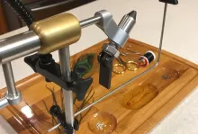
And as the pictures below show, the end result is looking good, the design is of course depending on personal taste. It has a classic look with the use of modern materials and very important: the grip on the hook is very good and with little force!


Operation of the vise
The clamping force of the o-ring on the rear side of the head causes the jaws themselves to open. With the angle adjustment screw we can rotate the tying head (and the hook shank) to the horizontal center line.
For the fine adjustment we unlock the fine adjustment screw of the adapter and slide the tying head up or down. With the hook thickness adjustment screw we can adjust the jaws to the desired hook shank thickness.
With the clamping screw we clamp the hook in its position and finally with little force we turn the adjustment screw to fasten the hook so that there is never too much pressure on the hook shank/bend. The small shallow grooves in the jaws provide excellent grip on the hook.
Tube fly adapter
Because I like making tube flies, I also made a tube fly adapter for this vise in style with the design, it will take needles up to 1.5 mm in diameter. With one of the hex tools we can quickly loosen the screw in the handwheel, after which the horizontal shaft with the tying head can be removed and the tube fly adapter can be inserted and the handwheel remounted and tightened with the tool.


The convenience of a removable tying head
The tying head can easily be removed thanks to the construction of the adapter with the fly still clamped in the jaws. This has the great advantage that the fly can be viewed closely from all sides and, if necessary, can easily be clipped and trimmed. Very nice when making deer hair flies.
In the near future I will design and make a bobbin holder rest and a set of fly tying tools for this vise with the same materials, so they will match the design.
With this article I wanted to share with you the development and manufacturing of my vise and the personal vision that I have on clamping a hook in a vise.
I hope you will appreciate the end result as much as I do.

Hand picked for this article


- Log in to post comments


Tom's vise
Tom, the vise is beautifull,I love it, but now it's time to drink coffee with me, after all the hours that you have worked on the vise.
Your wife, Fousjia.
Vise
Congratulations with your beautiful Vise. Seems to me very special to make this yourself ... if you have the skills. Both the wood and the metal looks very nice. I wonder if this is the one you actually use. What I missed in the text is the time you have spent in total. Keep up the good work!
Wood Vise
Tom, to say your vise is beautiful would be an understatement. Magnificent is a much better way to describe it! I too have a few hobbies. Fly tying, fly fishing and also wood turning. I never tried metal turning but wanted to try it. Putting all your expertise together to plan, build and implement your ideas into a magnificent vise is truly remarkable. Do you plan on selling your vises? How much would you charge? Best regards and good wishes. Richard Katzman, New York.
Tom's vise
Hello Michael,
Sorry for the late answer,thank you for the nice words about the vise! It was a big project and you asked in your comment how much hours I spent in making the vise. It is in the article , but I must commit it is hard to find , above the last picture of the article is a text where I say that I have spent about 220 workinghours in the vise! That is "not" including designing and developing the vise!
Best regards,
Tom Biesot.
Machining students would like to try as a student project
Tom:
Thanks for sharing your work. It's amazing.
I am an administrator at a community/technical college that has both machining and woodworking programs. My students would like to try and reproduce your vice as a class project. Is there anyway that we could discuss?
Doug Long
measurements
Wow, amazing work!
Would it be possible to have the measurements of such a wonderful vise? I'd like to have students build one.
Thanks a lot.
R
Congratulations Tom, when I
Congratulations Tom, when I saw the drawings, the metal and wood parts and the design I thought of a project in style Leonardo da Vinci, magnificent.
fabric
Hello
Which software used for the plan of objects. Thank you for the answer. Good week
Dominica